Section 1 – Understanding Capacity Classes in French Fry Production
Before selecting equipment or designing a layout, U.S. processors should first define their desired throughput range, as it determines layout spacing, utility demand, and automation requirements. In practical engineering terms:
- 2–6 TPH → Suited for entry-level or regional fresh/frozen processors
- 6–15 TPH → Mid-scale processing, requires defined wet/dry separation zones
- 15–30 TPH → Industrial capacity, demands loop or U-shaped plant layouts, utility recovery, and CIP routing planning from day one
Engineering Note: In the U.S., most processors planning above 15 TPH need early coordination with steam, electrical, air, and wastewater engineers — layout mistakes at this scale are expensive to modify later.
Section 2 – Standard Process Flow of a French Fry Line
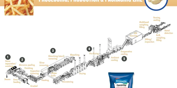
A typical French Fry or potato processing line follows this multi-stage progression. Each stage impacts conveyor layout, sanitation lanes, and floor drainage design:
- Raw Product Receiving and Infeed Washing
Removal of soil and debris with controlled water pressure to prevent product damage. - Stone / Grit Separation Zone
Usually positioned before peeling to prevent equipment wear or peeler chamber damage. - Peeling Stage (Steam or Abrasive)
- Cutting and Sizing Module
Uniform strip cutting using high-speed belt or drum cutters — needs vibration isolation to protect cutting accuracy. - Blanching Section
Temperature-controlled blanching ensures starch removal and prepares surface for frying. - Drying / Dewatering Zone
Critical for oil savings — excess moisture entering fryer increases oil degradation rate and operating cost. - Fryer or Par-Fry Tunnel
High heat zone; requires safe perimeter spacing and oil management access corridors. - Freezing Section (IQF Tunnel or Spiral Freezer)
Continuous infeed is essential — freezer backs up easily if upstream buffering is not designed correctly. - Inspection, Sorting, and Metal Detection
Optical sorting and final safety check before packaging. - Packaging & Film Sealing
Vertical baggers with scale -
Engineering Insight: A well-balanced line maintains continuous flow from blancher to freezer. Any pause in that sequence becomes a system bottleneck.
Section 3 – Layout Footprint Planning (By Capacity Level)
To avoid future plant modification costs, layout should be considered based on intended final scale, not initial installation size:
- 2–6 TPH Lines
- Straight-line layouts often feasible
- Minimal utility trenching required
- Best for compact processing rooms or retrofit installations
- 6–15 TPH Lines
- Requires zoned layout: raw, wet process, thermal process, packaging
- Room for internal conveyor buffers recommended to avoid freezer congestion
- 15–30 TPH Industrial Layouts
- Often designed in L-shaped or U-shaped loops for maintenance access
- OSHA clearance: maintain minimum 24 inches, ideally 36–48 inches clearance for all service access points
- Utility corridors must be designed before equipment anchor points are finalized
Sanitation Design Note: Plants under FSMA / USDA inspection must define wet process zones clearly — this affects drain placement, hose station positioning, and slope configuration.
Section 4 – Utility and Engineering Load Planning
For 2–30 TPH French Fry lines, utility infrastructure should be calculated early in the layout design phase. These are the core engineering loads to define before positioning machines:
Steam Requirement
- Required for blanching, steam peeling (if used), and heat exchange modules.
- Typical working range: 3–8 bar saturated steam
- Tip: Installing steam headers after equipment arrival leads to costly rework — plan piping grid before layout freeze.
Water Supply & Drainage
- Continuous wash zones and grit removal stages have high water turnover
- Design recommendation: Minimum 1.5-inch floor drains with 1–2% slope toward wet zones to prevent pooling under conveyors.
- Include CIP rinse points if planning for high sanitation automation.
Electrical Load
- Fryers, pumps, and freezer compressors carry the highest electrical draw
- For U.S. processors, 208/480V three-phase is standard — verify upstream grid capacity before finalizing plant layout.
Compressed Air Supply
- Used for diverter gates, sorting ejectors, and packaging pneumatics.
- Consistent air pressure prevents reject errors in optical sorting and film sealing.
Engineering Reminder: In 15+ TPH plants, utility corridors should run parallel to the conveyor flow, not crossing underneath. This makes future expansion and servicing significantly easier.
Section 5 – Common Bottlenecks in French Fry Line Layouts
Most underperforming French Fry lines have design bottlenecks traced back to layout errors, not machine limitations. These are the common causes:
- Freezer Infeed Stops – caused by insufficient buffer conveyor capacity upstream.
- Fryer Throughput Throttled – inconsistent cutting feed or wet product overload at fryer entrance.
- Peeling Delays – manual handling or non-automated bin feeding before peeler chamber.
- Overcrowded Maintenance Paths – less than 24-inch clearance around pumps, filters, or CIP panels leads to downtime during repairs.
- Drainage Conflicts – water accumulation under electrical panels due to poor layout slope planning.
Practical Insight: Most processors over-focus on equipment specs and underestimate material flow and access clearance, which are just as critical for hourly throughput.
Section 6 – Layout Optimization for Greenfield vs Retrofit Installations
For New (Greenfield) Plants
- Favor loop or U-flow layouts to keep wet and dry areas clearly isolated.
- Install utility mezzanines or raised access for piping — simplifies inspection and audit routes.
For Existing (Retrofit) Plants
- Retrofit layouts benefit from modular conveyor connections to work around fixed walls and drains.
- Avoid hard-plumbing utilities directly over machinery — use suspended manifolds or wall-mounted quick access rails.
Expansion Tip: Always leave room to extend conveyors by 30% of line length for future capacity increases. Almost every U.S. processor who scales regrets not planning this buffer.
Section 7 – Optional Automation Enhancements Worth Considering
For processors targeting higher efficiency and quality consistency, these add-on modules can be planned into the layout from the beginning:
- Optical Grading and Reject Systems — prevents non-uniform strips reaching fryer/freezer.
- Inline Quality Weighing or Vision Inspection — installed directly after cutting or blanching.
- Automated CIP Manifolds — enable cleaning cycles without manual disassembly.
- Automated Film Application and Packaging Control — reduces sealing errors downstream.
Final CTA Section – Request Layout Study
Need a plant-specific layout concept?
Submit your available floor space, target tonnage, and current utility setup, and we generate a preliminary line layout concept based on 2D process flow.
Contact us: sales@vegtechsystems.com